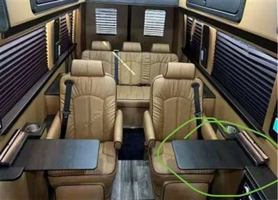
Design of electric seat lifting system
Front lift of the seat: 30mm-50mm
Seat rear end lift: 30mm-45mm
Lifting load capacity of the front part of the seat: 120kg
Seat rear end lifting load capacity: 120kg
8.1 program selection
In the design of the upper and lower lifting system of the seat, a screw mechanism is selected, that is, the motor is decelerated by the worm gear, and then a mandrel is inserted into the worm, and the worm wheel drives the rise and fall of the mandrel to realize the adjustment of the up and down movement of the seat.
Features of the screw mechanism:
1) Since the nut can only be moved by one lead when the screw rotates one turn, and the lead can be made small, the screw mechanism can be used as the adjustment mechanism, where a large reduction ratio is required in the machine, and the screw mechanism is used. The mechanism makes it easier to simplify the drive train.
2) Since the screw mechanism has a large reduction ratio, when a small torque is applied to the active member, a large thrust can be obtained on the driven member, that is, the screw mechanism has great mechanical advantage, and thus Suitable for use in jacks and presses.
3) Choosing a suitable helix angle can be a self-locking function of the screw mechanism. For example, the lifting screw of the workbench of the planer has self-locking property, so that the workbench can not be prevented from falling due to its own weight, and the lifting of the seat is more Need to be self-locking.
In addition, the screw mechanism has the advantages of simple structure, stable transmission and no noise. The shortcomings of the screw mechanism are mainly the low efficiency of the sliding screw, especially the efficiency of the self-locking screw mechanism is less than 50%.
8.2 Screw design calculation
The screw can be made of A5, A6 or 35-45 steel. When high quality carbon steel is used, heat treatment is needed to enhance the wear resistance of the thread. The screw is mostly trapezoidal thread.
When the screw is raised to the high position, the force is the most unfavorable. The screw is a pressure rod and is subjected to pressure and torque. Therefore, the thread is calculated according to the compressive strength, stability and self-locking conditions.
8.2.1 Compressive strength calculation
When the screw is working, it is subjected to both pressure and torque. In order to simplify the calculation, only the effect of the pressure can be recorded, and the reduced compressive stress required is used. The compressive stress and strength conditions of the screw are:
Where: d1 - screw inside the mm
Q - total axial force acting on the thread N
Because the seat lift load capacity is 120kg, the gravity acting on one of the two screws is 120/2*10=600N
[σ]——Requires compressive stress, which can be 5~8KN/mm for carbon steel
In the substitution type, available
D1 selects standard thread 8mm.
8.2.2 Calculation of stability
When the screw is at the highest position, it can be regarded as the lower end fixed, the upper end is free, and the diameter is d1. The checkpoint knows its end coefficient μ=2, and its stability can be checked by the following formula: nsc=Qc/Q≥ Ns
Where: scn——the calculation safety factor of screw stability
Qc——the critical pressure of the screw
Ns - design safety factor for screw stability
The design safety factor of screw stability ns can be 3~5, so ns=4, and the critical load Qc of the screw should be calculated by different formulas depending on the flexibility of the screw as λ=μL/ρ (where L is The calculated strength of the screw, taking the lifting height of the seat is 40mm, the radius of gyration of the cross section of the ρ screw, ρ=d1÷4=2mm, λ=2×40÷2=40
Because 40λ=less than 100, the material is 45 steel, the strength limit σ≥48k/cm2, take
Further, nsc = Qc / Q ≥ ns = 600, so the screw has good stability.
8.2.3 Accounting of self-locking ability
Because the self-locking condition is such that it has a reliable self-locking ability, at least the spiral angle of lift should be less than 1 degree of the equivalent friction angle. The equivalent friction coefficient fv=0.08~0.1., the corresponding equivalent friction angle should be
8.2.4 parameters
Check the Mechanical Design Handbook Table 3-8, the basic dimensions of the trapezoidal thread:
Nominal diameter d 8
Pitch p 2
External thread diameter d3 5.5
Inner diameter of inner/outer thread D2/d2 7
Internal thread diameter D4 8.5
Internal thread diameter d4 6
8.3 Height adjustment motor selection
8.3.1 Selection parameters
According to the requirements, the height of the seat is 40mm, the time required for the whole movement is 8s, and the lifting speed of the seat is v=s/t=5mm/s.
8.3.2 Torque of the screw
The axial force Q of the screw has been calculated previously, according to the formula:
8.3.3 Calculating the torque of the motor
M electricity *i* η=M wire
Here, the worm and worm speed reduction ratio is 62, and the transmission efficiency is 0.8.
M electricity = 119g × cm
Since the motor is a two-axis output DC motor of the sz series, the torque is:
M total = 2M electricity = 290g × cm = 0.290g × m
For economical convenience, the motor with the same design as the system is selected to meet the required torque.
8.3.4 Checking the selected motor torque
According to the formula:
Where: Td——output torque of electric shaft Nm
T1 - the input torque of the working shaft, which is equal to the torque T on the turbine
The formula is deformed as follows:
Through the above calculations, it is indicated that the selected motor is satisfactory, so the motor of the horizontal moving part is a permanent magnet type two-axis output DC motor of the 45sz01 type.
Check "China Machinery Design Industry Standard Compilation·Gear and Gear Transmission Volume (Bottom)" SWL Worm Gear Lift Form, Parameters and Dimensions, JB/T8809-1998. Select SWL2.5 based on motor speed, power, and lift speed.
The relevant parameters are as follows:
Maximum lifting capacity: 25KN
Maximum pulling force: 25KN
Worm gear ratio 24:1
Worm stroke per revolution: 0.250mm
Maximum elongation of the screw during tension load: 1500mm
Maximum allowable power: 0.55Kw
General ratio total efficiency: 23%
Lubricating oil quantity: 0.1kg
Weight without stroke: 7.3kg
Weight per worm of worm: 0.45kg
Note: 1. The maximum allowable power is the parameter under the condition that the ambient temperature is 20C° and the working duration is 20%/h.